In the last part of this 3D integration VFX series, I showed you how to use the 3D camera tracker and how to export your tracking data ready for import into your 3D program.
In this tutorial I will show you how to import that data into your 3D program, create some virtual elements and render out all of the layers you will need for compositing everything together.
I am using 3dsMax for this tutorial, but it doesn’t really matter which specific 3D program you use. You should use to one you’re most comfortable with. The theory behind each step should apply to all comparable products like Maya or Cinema 4D.
Setting up your 3D project
Create a new project in 3dsMax and go to your render settings. Set the output width and height to match the footage you shot for the 3D integration effect. I shot the UFO scene in 1080p so I will go with 1920×1080. Often it is useful to work in half or quarter resolution until you are ready to export the final render simply to make the iterative workflow faster.
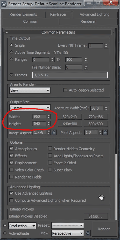
Set up the renderer you want to use. I am going with the Default Scanline Renderer for this tutorial.
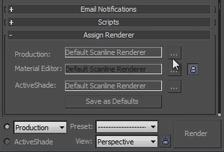
If you have vRay – and know how to use it properly – I highly recommend it, but that could be a whole new tutorial in itself and I don’t want to over-complicate things here.
Close your render settings.
Importing the camera tracking data
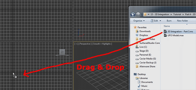
First, we want to import the camera tracking data we exported in the last part of this tutorial into 3dsMax. The file we exported is a .ms file and you can import it by simply dragging it into one of the viewports in 3dsMax and selecting ‘Open File’ from the context menu.
Ensure that the length of your animation in 3dsMax matches the number of frames in the composition in After Effects. If you have a mismatch, the rendered elements might not fit properly onto your original footage. The UFO clip I exported had 240 frames and my 3dsMax project has been set to the same number when I imported the .ms camera data.

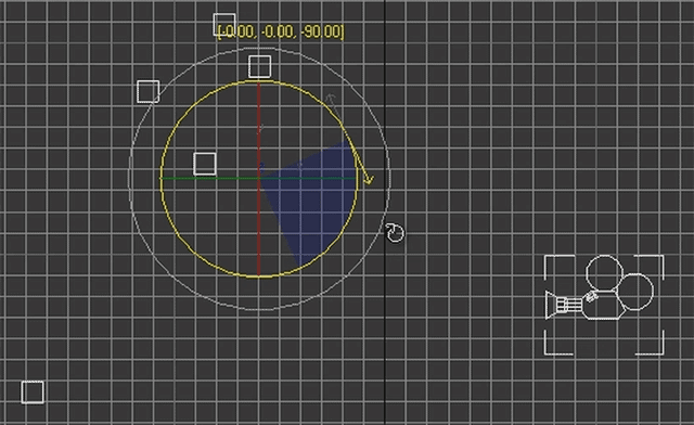
A new camera and one dummy object for each null object we exported from After Effects will appear. Note that the camera is aiming downwards, which does not really match the way we filmed the scene. This is happening because After Effects and 3dsMax use different coordinate systems. This is the left viewport in 3dsMax.
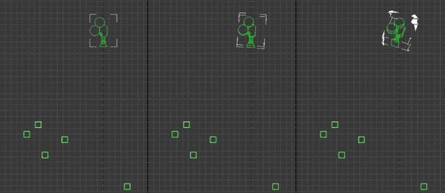
We will fix that up in a moment, but for now, select the camera and go to the modify tab to reveal the camera settings. To ensure the rendered 3D elements will match the footage we shot, we have to match up the settings of the virtual camera to the same settings we used for our real life camera. That is why we wrote down all of the settings when we shot the scene :)

Again, if you have vRay, it might be worth switching out the generic camera for a vRayPhysicalCam because it has a lot more things you can configure. I assume that if you are using vRay you will know how to do that anyways :)

Let’s fix up the fact that the camera is pointing downwards at the ground.
Select the camera and all the dummy objects in the scene and group them together.
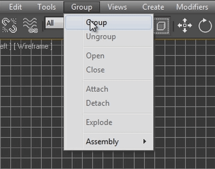
Now rotate the group by 90 degrees to have the camera face the correct way. Do not ungroup the elements or their relative positions and keyframes might get misaligned!
Now select your perspective viewport and set it to show the view of the camera.
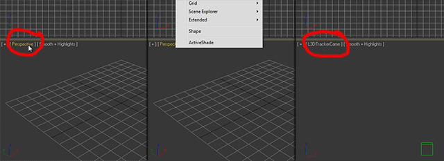
If you play back your animation now, the camera should execute the same motion as the camera we created in After Effects. It should match up with the movements of your real life camera from when you filmed your footage.
All the null objects should move exactly like they did in After Effects.

If your null objects do not move exactly the same way they did in After Effects, something might have gone wrong in the process and you will have to figure out where things went wrong. Once they match the clip in After Effects precisely we’re ready to create our 3D elements.
However, before we get to that, let us set up the background of the viewport for the camera to use our original footage. This way we can see how the null objects and any 3D objects we create will sit in our original scene.
Setting up the viewport background
Select the viewport that is using the camera’s view, go to the menu bar and select Viewport -> Viewport Background -> Viewport Background.
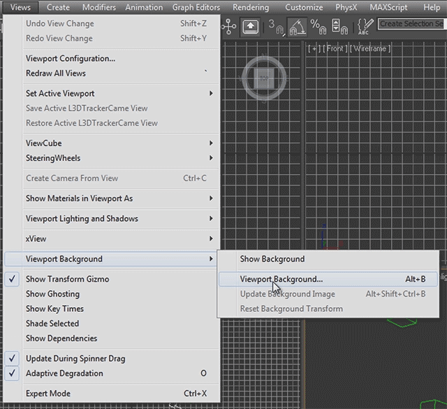
I have exported the original clip I had in After Effects from the same composition with the same time range I used to track my camera, as a JPEG sequence. This does not need to be very high quality, just good enough so you can see what is going on. Select the first image in the sequence, tick the ‘Image Sequence’ check box and click OK.
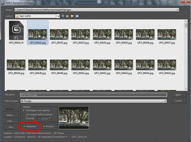
Also tick the ‘Animate Background’ check box for the viewport background options so it updates properly as you scrub through your animation.
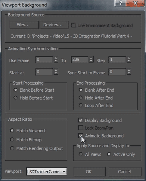
You should now see your original scene directly in the viewport of the camera and, playing back the animation, the dummy objects should track the footage like the null objects did in After Effects. If they do not, you may have mismatched frame numbers in your exported camera data and your background image sequence.

Now we’re ready to create our 3D elements!
Creating the 3D elements
Since I suck at modeling in 3dsMax, I went online and found this free UFO model on Turbosquid.
When using any assets from the Internet, ensure that you have permission to use it for whatever it is you are intending to use it and that you credit the author if required.
To import the model, simply drag the file from your file browser into one of the viewports in 3dsMax and select the ‘Merge File’ option from the context menu.
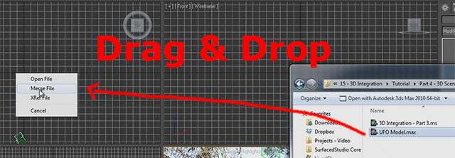
Bam! You should now have a UFO in your scene.
Position the UFO and scale it so it sits right in the opening in the foliage as indicated by our dummy objects. Remember that the dummy objects do not reflect the actual 3D positions of the branches, they only track the trees when seen from the camera’s point of view.
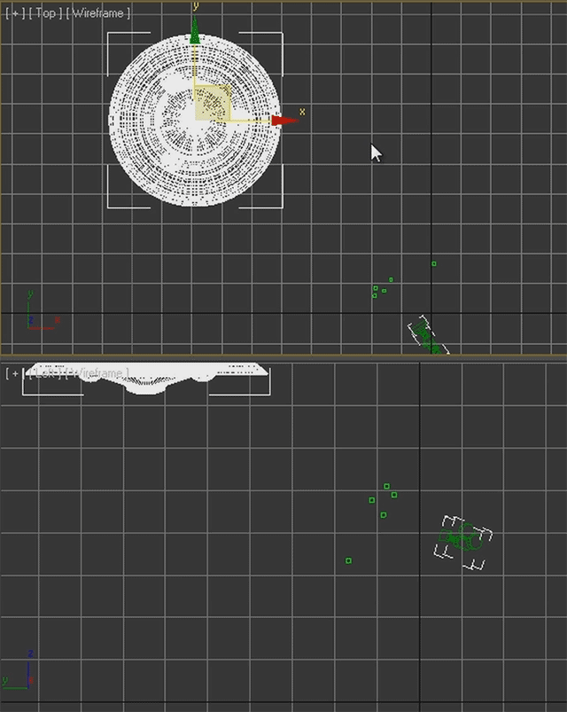
Playing back your animation, the UFO should now sit nicely in your scene and follow the camera’s movement.

Because I think this looks a little boring, let’s animate the UFO so it appears to be approaching the scene, slowing down and finally coming to a stop just above the tree line when the camera has finished aiming up.
Go to the time position where the camera has just finished panning up and click the ‘Set Key’ switch at the bottom of the interface. Click the ‘Create Keyframe’ button to the left (the button with the big key icon) to create your first keyframe for the UFO in its current position.
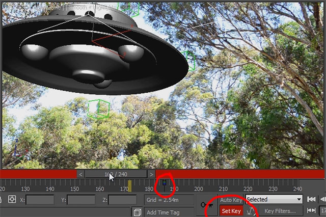
Move the time slider back until your UFO is entirely off screen and, using the top and side views, move the UFO back a little bit and rotate it around the Y axis. Now click the create keyframe button again and, this is important, exit keyframe mode by disabling the keyframe mode switch.
Playing back the animation now, the UFO should approach, spinning slightly, slow down and finally come to a stop just above the opening in the foliage.

Now, very few UFOs are a matte grey colour (or so I presume, at this point it’s really anyone’s guess!), so you should probably assign a few materials to your model to make it look more realistic. You can do all of that in the Material Editor which you can open up by pressing the ‘m’ key on your keyboard.
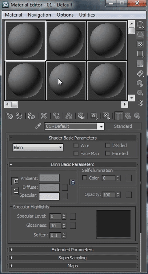
The material editor warrants a whole (or many) tutorials in itself but I won’t get into any detail on it here. For now, I will just leave my UFO plain and grey. Just imagine the aliens did a bad paint job or wanted their floatation devices to match their skin colour… :D
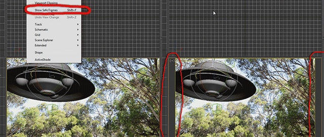
With that done, let us quickly enable an important option in our camera viewport. This option is the ‘Show Safe Frames’ option and it will lock the viewports aspect ratio to what you specified in your render settings and ensure that the background image won’t get stretched out of proportion.
Setting up lighting
Because we will compose our rendered UFO with the original footage we shot, we need to make sure that the lighting matches. Our original scene was lit mainly by the sun so let’s set up a light to represent the sun in our 3D scene.
Create a free direct light and position it far above the UFO and scale it up so the cone of the light encompasses the entire scene. Aim it at the UFO so the light comes in at the same angle as the sun in the original scene.
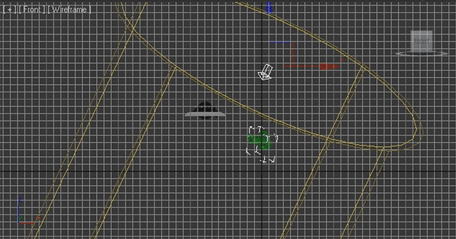
If you select the light and go over to the ‘Modify’ tab, you should be able to change its settings to better match your sun. You may want to adjust the intensity, enable shadows and set the colour to something a little bit yellow.
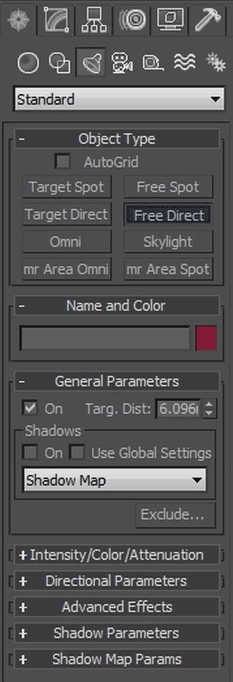
How you set up your lights will depend on your actual scene so these are just rough guidelines. Remember, the more accurately you set up your virtual lights to match the original footage the better the 3D integration effect will work.
Let’s do a test render of our scene!
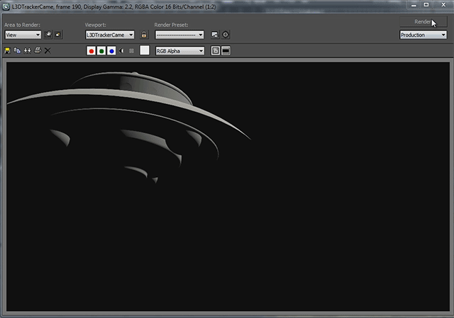
That’s not bad, but the underside of the UFO is entirely black. In the real world – assuming it contained aliens and UFOs – the sunlight bouncing off the ground would probably illuminate the UFO a little from the bottom. If you want to go all out, you could set up global illumination to simulate this effect, but if you’re cheap like me you can fake it by setting up a simple omni light underneath the UFO :)
Create a simple omni light and position it below the UFO.
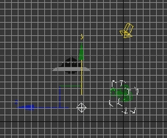
I’ve set my light to be very soft because I just want to brighten the underside of the UFO a little bit. Rendering the UFO again it should look a lot more realistic! Note that the bottom of the UFO is lit only a tiny bit so the shape of the UFO comes through.
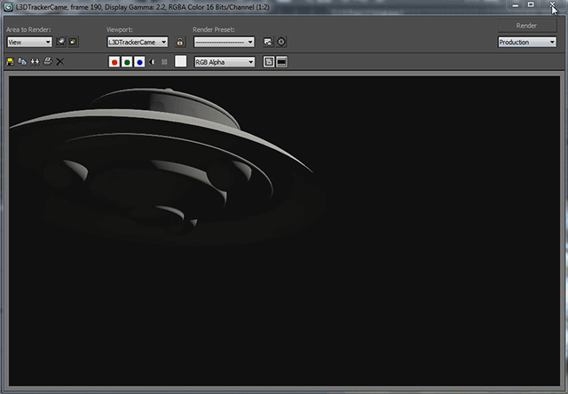
Now it’s time to render! But before we hit the render button, there’s one more thing I want to cover: exporting individual layers separately.
Rendering Individual Render Passes
It may not be necessary for every 3D integration VFX you create, but quite often you find yourself in a situation where you want to render out different layers of your 3D scene separately to gain more control over how they are composited in your final effect. These layers can be the so-called beauty pass (full render), shadows only, alpha information, zDepth, illumination and much much more. These layers are usually exported by using separate render passes.
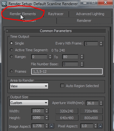
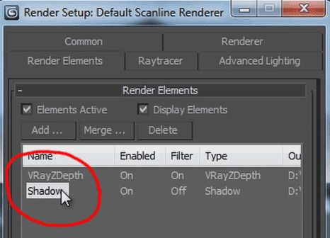
In 3dsMax, these render passes can be configured in the ‘Render Elements’ tab in your render settings dialog.
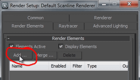
Besides your beauty render, you can add individual render passes by clicking the ‘Add’ button in the Render Elements section.
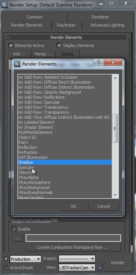
Note that 3dsMax provides a very large list of individual render passes that you can export. The list might differ slightly depending on your version of 3dsMax and which plug-ins you have installed.
Of particular interest to me are usually the Shadow and zDepth passes.
What is a Z-Depth pass and why do I need it?
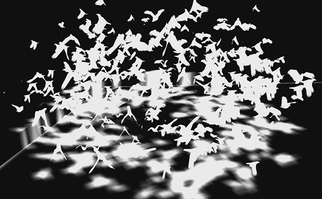
A Z-Depth pass is a greyscale image that provides depth information by representing elements closer to the camera with lighter and the objects further away from the camera darker.
Here is the Z-Depth layer I rendered out for my Dissolve Into Crows effect.
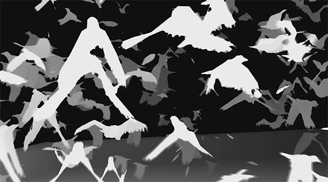
Note that the crows closer to the camera are very bright and the crows further away from the camera are darker. A Z-Depth pass has a min and a max distance setting that control how close an element has to be to become 100% white and how far it has to be to be 100% black. You have to take care to set up your min and max values for the Z-Depth render pass to encompass your entire scene to get a smooth greyscale image.
Why render a Z-Depth pass?
The Z-Depth pass can help you during compositing and is usually used as a matte (or other type of invisible control) layer to integrate 2D layers with your 3D footage. Now of course during compositing you are exclusively dealing with 2D layers, but using the Z-Depth pass you can apply depth information to your effect :)
Configuring your Z-Depth pass
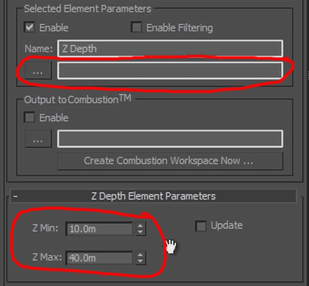
Once you added the Z-Depth pass, you need to configure it and specify where you want your render pass files to be saved. I usually export them next to my beauty pass with a “_zDepth” suffix. Additionally, be sure to set the Z min and Z max values according to your scene dimensions.
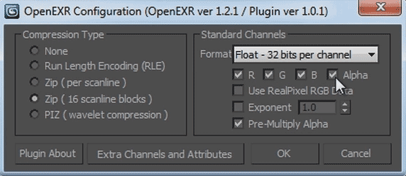
Just like the beauty pass, I like to use the OpenEXR file format in full 32 bit for all of my render passes. It will give you a lot more quality and control during compositing then a Quicktime or MPEG movie or a JPEG sequence would give you.
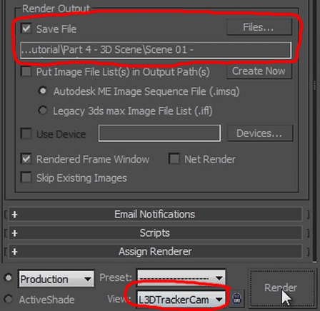
Finally, return to the main render settings and ensure that you tick the ‘Save File’ check box and specify an output path for your beauty render. Ensure the export quality is set to ‘Production’, select the viewport that uses the camera we imported from After Effects and hit the Render button :)
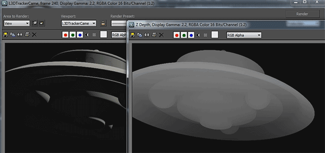
This might take a while depending on the complexity of your scene, the number of render passes you selected and the processing power of your computer, but you should end up with a full render of your beauty pass as well as any other render passes you set up. For this example I have my UFO and the Z-Depth pass for the UFO here.
We are now ready to take our rendered elements back into After Effects and composite them onto our original footage… but how do we deal with shadows?
But what about shadows?
Ok, ok! In the UFO scene, the shadows were falling away to the left side and the UFO was far above the treeline so we didn’t really need to concern ourselves with having our 3D elements casts shadows.
Of course, depending on the lighting of the original shot and depending on the 3D elements we want to integrate into our scene, they might have to cast shadows onto the ground, the walls or even the actors.
First of all, you have to enable the shadows for all the lights in your scene. By default, 3dsMax lights will have their shadow option turned off. You may also want to increase the shadow map resolution if you are using shadow maps to ensure that the shadows created are nice and smooth.
Here is a quick render of the crows from my Dissolve Into Crows effect, including the pier geometry and the shadows they cast.
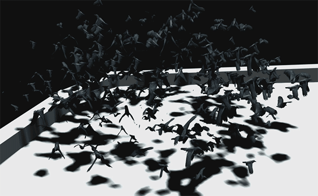
Unfortunately, we cannot take this image and composite it onto our original footage because it has the 3D geometry of the pier in it! But without the pier geometry, we wouldn’t be able to render any shadows. So how is this supposed to work?
The answer to the question is: matte shadow or shadow catcher materials!
Matte shadow materials are invisible when rendered, but they can be configured to receive shadows cast by other 3D elements in the scene. By placing this material on any geometry in our scene that needs to receive shadows, we get a final render that does not show any geometry, but it does show the shadows for our 3D elements as if they were cast onto the geometry.
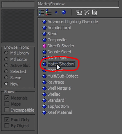
In the material editor, you can create a ‘Matte/Shadow’ material by selecting it from the available material list.
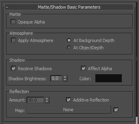
Ensure that you tick the ‘Receive Shadows’ as well as the ‘Affect Alpha’ check boxes on the material and then assign it to the geometry in your scene.
Here is the scene from my Dissolve Into Crows effect where I have assigned the matte shadow material to the pier.
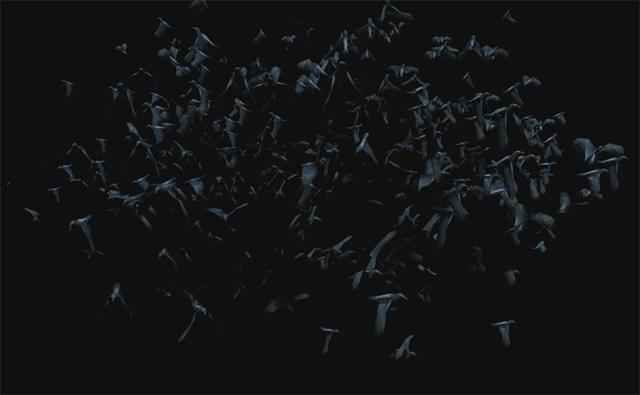
Huh? No pier, no shadows? Don’t worry, the shadows are black – as they should be – and you only have to toggle the show alpha switch in the render preview window to see that our beauty render now includes the shadows for the crows :)
Of course, just like with all render passes, you can decide to render out the shadows as a separate layer. Just like the Z-Depth pass, you can configure this render pass in the ‘Render Elements’ tab in your render settings.
And that is the basics of creating a scene in 3dsMax and rendering it out, ready to be composited onto your original footage in After Effects!


